 b.stefanuk.ca
UML Diagrams Simplified
Unified Modelling Languages is a standardized notation for modelling an object oriented system
Below is a tree of all the the types of diagrams within the UML framework. 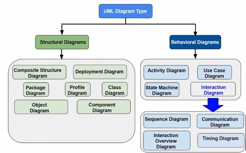
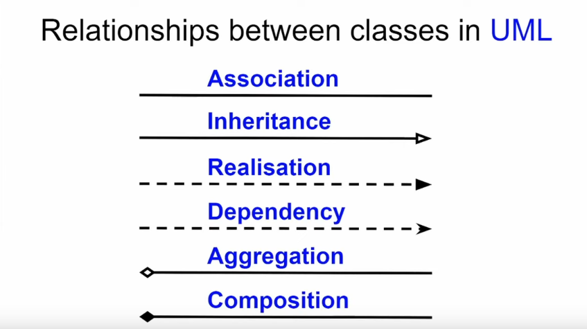
- Class diagram
- Central modelling techniuqe for OOM, most important relationships: association, inheritance, aggregation
- Conceptual perspective
- Specification perspective
- Implementation perspective
- Central modelling techniuqe for OOM, most important relationships: association, inheritance, aggregation
Data Flow Diagram
Reference the Wikipedia article.
Useful in Writing Design Documents within the Detailed Design section. Consists of 4 components, as depicted below. 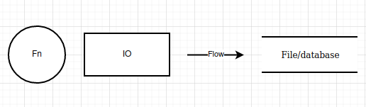
Think about how the various functions and structures will pass data, but don't go overboard on the design, this will have to be updated after implementation because it will be wrong, somewhat.
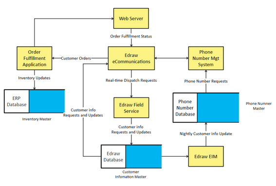
Here is an example of a Data Flow Diagram for an ERP inventory system.